- 您现在的位置:买卖IC网 > Sheet目录1992 > CYW305OXC (Silicon Laboratories Inc)IC CLOCK W305 SOLANO 56SSOP
Frequency Controller with System Recovery for Intel Integrated
Core Logic
W305B
........................ Document #: 38-07262 Rev. *B Page 1 of 20
400 West Cesar Chavez, Austin, TX 78701
1+(512) 416-8500
1+(512) 416-9669
www.silabs.com
Features
Single chip FTG solution for Intel Solano/810E/810
Programmable clock output frequency with less than
1 MHz increment
Integrated fail-safe Watchdog timer for system
recovery
Automatically switch to HW selected or SW
programmed clock frequency when Watchdog timer
time-out
Capable of generating system RESET after a Watchdog
timer time-out occurs or a change in output frequency
via SMBus interface
Support SMBus byte read/write and block read/write
operations to simplify system BIOS development
Vendor ID and Revision ID support
Programmable drive strength for SDRAM and PCI
output clocks
Programmable output skew between CPU, AGP, PCI
and SDRAM
Maximized EMI suppression using Cypress’s Spread
Spectrum Technology
Low jitter and tightly controlled clock skew
Two copies of CPU clock
Thirteen copies of SDRAM clock
Eight copies of PCI clock
One copy of synchronous APIC clock
Three copies of 66-MHz outputs
Three copies of 48-MHz outputs
One copy of double strength 14.31818-MHz reference
clock
One RESET output for system recovery
SMBus interface for turning off unused clocks
Key Specifications
CPU, SDRAM Outputs Cycle-to-Cycle Jitter: ............. 250 ps
APIC, 48-MHz, 3V66, PCI Outputs
Cycle-to-Cycle Jitter:................................................... 500 ps
CPU, 3V66 Output Skew: ........................................... 175 ps
SDRAM, APIC, 48-MHz Output Skew: ....................... 250 ps
PCI Output Skew: ....................................................... 500 ps
CPU to SDRAM Skew (@ 133 MHz) ....................... ± 0.5 ns
CPU to SDRAM Skew (@ 100 MHz) ................. 4.5 to 5.5 ns
CPU to 3V66 Skew (@ 66 MHz)........................ 7.0 to 8.0 ns
3V66 to PCI Skew (3V66 lead) .......................... 1.5 to 3.5 ns
PCI to APIC Skew..................................................... ± 0.5 ns
1. Internal 100K pull-up and 100K pull-down resistors present on inputs marked with * and ^ respectively. Design should not rely solely on internal pull-up resistor
to set I/O pins HIGH or LOW.
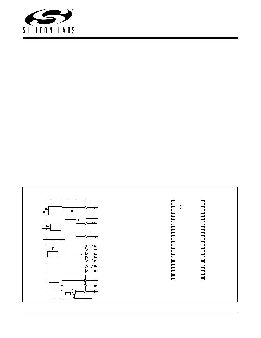
Block Diagram
Pin Configuration[1]
VDDQ3
VDDQ2
PCI1/FS1
XTAL
PLL REF FREQ
PLL 1
X2
X1
REF2X/FS3
PCI3:7
48MHz/FS4
24_48MHz/SEL24_48MHz#
PLL2
OSC
VDDQ3
SMBus
SDATA
Logic
SCLK
3V66_0:2
CPU0:1
APIC
Divider,
Delay,
and
Phase
Control
Logic
3
VDDQ3
2
SDRAM0:12
13
RST#
PCI0/FS0
PCI2/FS2
/2
(FS0:4)
5
48MHz
GND
VDDQ3
REF2X/FS3^
X1
X2
VDDQ3
3V66_0
3V66_1
3V66_2
GND
PCI0/FS0^
PCI1/FS1^
PCI2/FS2^
GND
PCI3
PCI4
VDDQ3
PCI5
PCI6
PCI7
GND
48MHz
48MHz/FS4^
24_48MHz/SEL24_48MHz#*
W
305B
VDDQ2
APIC
GND
VDDQ2
CPU0
CPU1
GND
SDRAM0
SDRAM1
SDRAM2
VDDQ3
GND
SDRAM3
SDRAM4
SDRAM5
SDRAM6
VDDQ3
GND
SDRAM7
SDRAM8
SDRAM9
SDRAM10
VDDQ3
GND
56
55
54
53
52
51
50
49
48
47
46
45
44
43
42
41
40
39
38
37
36
35
34
33
1
2
3
4
5
6
7
8
9
10
11
12
13
14
15
16
17
18
19
20
21
22
23
24
25
26
27
28
32
31
30
29
VDDQ3
SDATA
GND
VDDQ3
SDRAM11
SDRAM12
RST#
SCLK
发布紧急采购,3分钟左右您将得到回复。
相关PDF资料
DAC5674IPHPG4
IC DAC 14BIT 400MSPS 48-HTQFP
DAC7621EBG4
IC SNGL 12BIT PARALLEL D/A 20SSO
DAC7801KPG4
IC DUAL 12BIT CMOS DAC 24-DIP
DAC8043AESZ
IC DAC 12BIT MULT SRL INP 8SOIC
DAC8043GP
IC DAC 12BIT MULTIPLY CMOS 8-DIP
DAC8221GP
IC DAC 12BIT DUAL W/BUFF 24-DIP
DAC8222GPZ
IC DAC 12BIT DUAL W/BUFF 24DIP
DAC8229FSZ-REEL
IC DAC 8BIT DUAL V-OUT 20SOIC
相关代理商/技术参数
CYW305OXCT
功能描述:时钟发生器及支持产品 Legacy-Sys Clk Intel RSolano Chip W305B RoHS:否 制造商:Silicon Labs 类型:Clock Generators 最大输入频率:14.318 MHz 最大输出频率:166 MHz 输出端数量:16 占空比 - 最大:55 % 工作电源电压:3.3 V 工作电源电流:1 mA 最大工作温度:+ 85 C 安装风格:SMD/SMT 封装 / 箱体:QFN-56
CYW311OXC
功能描述:时钟发生器及支持产品 Sys Clk VIATM Pro266 DDR Chipset W311 DS RoHS:否 制造商:Silicon Labs 类型:Clock Generators 最大输入频率:14.318 MHz 最大输出频率:166 MHz 输出端数量:16 占空比 - 最大:55 % 工作电源电压:3.3 V 工作电源电流:1 mA 最大工作温度:+ 85 C 安装风格:SMD/SMT 封装 / 箱体:QFN-56
CYW311OXCT
功能描述:时钟发生器及支持产品 Sys Clk VIATM Pro266 DDR Chipset W311 DS RoHS:否 制造商:Silicon Labs 类型:Clock Generators 最大输入频率:14.318 MHz 最大输出频率:166 MHz 输出端数量:16 占空比 - 最大:55 % 工作电源电压:3.3 V 工作电源电流:1 mA 最大工作温度:+ 85 C 安装风格:SMD/SMT 封装 / 箱体:QFN-56
CYW312OXC
制造商:SPECTRALINEAR 制造商全称:SPECTRALINEAR 功能描述:FTG for VIA⑩ K7 Series Chipset with Programmable Output Frequency
CYW312OXCT
制造商:CYPRESS 制造商全称:Cypress Semiconductor 功能描述:FTG for VIA⑩ K7 Series Chipset with Programmable Output Frequency
CYW320OXC-3
功能描述:时钟合成器/抖动清除器 Legacy, W320-03 datasheet RoHS:否 制造商:Skyworks Solutions, Inc. 输出端数量: 输出电平: 最大输出频率: 输入电平: 最大输入频率:6.1 GHz 电源电压-最大:3.3 V 电源电压-最小:2.7 V 封装 / 箱体:TSSOP-28 封装:Reel
CYW320OXC-3T
功能描述:时钟合成器/抖动清除器 Legacy, W320-03 datasheet RoHS:否 制造商:Skyworks Solutions, Inc. 输出端数量: 输出电平: 最大输出频率: 输入电平: 最大输入频率:6.1 GHz 电源电压-最大:3.3 V 电源电压-最小:2.7 V 封装 / 箱体:TSSOP-28 封装:Reel
CYW320OXC-4
功能描述:时钟合成器/抖动清除器 Legacy, W320-04 datasheet RoHS:否 制造商:Skyworks Solutions, Inc. 输出端数量: 输出电平: 最大输出频率: 输入电平: 最大输入频率:6.1 GHz 电源电压-最大:3.3 V 电源电压-最小:2.7 V 封装 / 箱体:TSSOP-28 封装:Reel